Petter-Light sets Copyright - Roland Craven 2008 The support and encouragement of Philip Thornton-Evison is freely acknowledged as is the help of: Graham Howland, Dave Shortland.
|
Like the previous documents on the M and S types this a hostage to fortune. It is based on evidence I have seen and on discussions with knowledgeable people. This section will remain under development for some time .If you are able to fill a gap, and either complement or contradict any of my conclusions, then please contact me. Feedback is always appreciated whether it be praise or criticism or simply thanks.
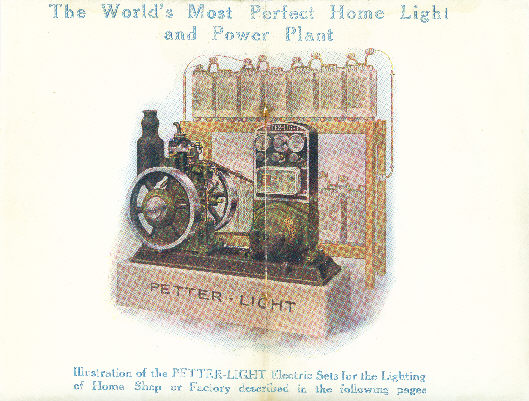
Sets under this brand-name were offered from c1920 until c1939
and around 5000 set numbers were used. Numerically the 3hp set has much the
higher survival rate although the sets are by no means common today. 50vdc is
the most common voltage.
Sets were also rebadged and sold under a variety of other names including; GEC,
Verity, and Rashleigh-Phipps. Badged sets in sizes from 2 1/2hp-6hp appear to
have the "Petter-Light" legend ground out and the OEM's badge screwed in its
place. The 1 1/2-2hp direct-coupled sets seem never to have had any legend cast-in to the base.
Sets were available in both belt-driven and direct-coupled form. Engines for the
former usually having spoked flywheels and the latter usually having solid
flywheels.
The majority were tank-cooled although radiator-cooled sets were made.
Engines in the M & S range from 1 1/2hp to 8hp were used (500 Watts to 4
kilowatts, and 32vdc-220vdc). Larger engines in the S type range were also used
but not marketed under the Petter-Light brand.
The sets were sold both complete and in component form with the option of
buying; engine, baseplate, dynamo and switchboard separately. It is not clear
whether this option was available to retail Customers or only to wholesalers,
however Petters were famously flexible so it was probably generally available.
Similarly all sorts of odd variations occur, most obviously to the oiler fitted
to the engine.
Most sales were of sets intended for battery charging and in these the dynamo is
usually shunt-wound and the dynamo-mounted switchboard used. Battery charging
sets usually incorporate a starting winding and a spring-loaded starting-switch
on the board. Direct-coupled charging sets, possibly because of the vibration,
used a wall-mounted switchboard.
Those intended for direct lighting employed a compound-wound dynamo, without
starting winding, and either wall-mounted or much simpler dynamo-mounted
switchboard (as on the "Workshop" set).
Dynamos
Were bought in from at least eight makers with some disappearing and reappearing
more than once. The known ones include; Newtons, Crompton-Parkinson, Crypto,
Metropolitan-Vickers, GEC, Verity and EPE (Electrical Power Engineering Co. Ltd. of
Birmingham). It is possible that this latter dynamo was only used by a badge
seller
There is a large range of features which vary both by maker and
over time. Some have fans and others not, and both ball bearing and ring-oiled
plain bushes appear. Two brushes or two pairs and interpole windings for spark
reduction all come and go. In some early cases the original maker's plate
remains affixed but they were normally removed by Petters. The makers dynamo
serial number can sometimes be found stamped into the shaft end. This practice
may be unique to GEC.
Each dynamo, with the exception of those fitted to 1 1/2-2hp
direct-coupled sets, should bear a Petters plate stating its Petter-Light
number, voltage and sometimes current (amps) although the latter is most often
left blank. Normally the drive was taken from the non-starting (pulley) side of
the engine to a crowned and flanged pulley on the dynamo. Note where the
flywheel is employed for drive it is normally, but not always, crowned.
Unless the dynamo has been dismantled the P-L plate should be on the side
furthest from the engine. Typical pulleys are designed, when driven from the
flywheel at the engines rated speed, to give a dynamo speed in the range
1300-1850 rpm. Again there is much variation but 1450rpm appears to be the most
common.
Switchboards
The earliest were cast-iron, somewhat crude and possibly made in-house by
Petters. By 1922 at least, and possibly earlier, the familiar cast
aluminium/slate board had been contracted out to Cromptons. The style remained
very similar until about 1934 although several makers were used and many minor
changes incorporated. Not all these changes are a boon to latter-day restorers;
for example the early rheostats were wire wound on enamelled steel tube - hard
to damage and easy to repair. The later rheostats were an array of
asbestos/resistance wire mats which are fragile, subject to corrosion and swine
to repair.
From about 1934 the board was redesigned in a new sloping front form. Although
probably much cheaper to produce the same basic elements remain.
The switchboards have a serial and makers code stamped into the top of the front
arch. Later GEC boards also quote the rated voltage and wattage.
The known codes are: none- Cromptons, G - GEC, R - thought to be R&H hands, Y -
Ray Engineering (Note: Y is an odd choice which suggests that R had already been
used as suggested above).
The board makers also bought in the meters and thus we get for example GEC boards with
meters by Crompton, EEC and GEC themselves.
Dismantling of the boards is best avoided but if it can't be avoided I would
suggest removing the back only with copious notes, photographs and labels. Clean
all moving contacts and connections. Check for broken wires. Note the knobs on
the front are held in with pins and are either wood or an early plastic. Both
are very fragile. The look of the knobs can be improved with careful cleaning
and black shoe polish.
Batteries
were originally racks of 2vdc lead-acid cells in large glass containers. Each
needed to be charged at about 2.3-2.7v hence the 50-70-vdc rating of the dynamo.
The number of cells varied but for 50vdc would most likely be 27 so as to give a
nominal 48vdc when partially discharged.
Connections
The following is the typical wiring for a shunt-wound dynamo mounted board ONLY.
The dynamo should have four tails emerging and these represent connections to
the board terminals labelled D+ D- SH and SER.
If the brushes are isolated by slipping dry paper under the brushes then an
ohm-meter should show two separate windings each with an end to a brush: one of
about 20-40 ohms (this is the Shunt winding and the free end is connected to the
SH terminal of the board). The other of about 1-3 ohms. The latter is the
starting or series winding and the free end should be connected to the SER
terminal on the board.
I have found generally that the rheostat should have a maximum resistance
roughly equal to that of the shunt winding, and give a smoothly changing reading
between that and Zero.
The two other leads from the dynamo are directly connected one to each brush and
are (D)ynamo + and (D)ynamo -.
Spinning the dynamo, in the driven direction, by hand with a volt meter across
D+ and D- should give a few volts and indicate both the polarity and whether all
is probably OK.
The cut-out
Is to prevent a battery from motoring a stopped engine. It was only fitted to
battery-charging sets and sits in its glazed housing on the front of the board.
When the engine is running a current passes through a coil and pulls the moving
arm into the two wells. The wells were originally filled with mercury and
completed the charging circuit. If the engine stops then the arm rises and
breaks the circuit.
The board is designed so that the load (L+ and L-) is taken from the battery via
the right hand switch and fuse. (the LH switch and fuse are in
the dynamo output). The batteries would normally be connected to B+ and B- with
the end-cells connected to B+2.
To run without batteries it is necessary to connect the load to the B+ and B-
terminals and arrange to by-pass the cut-out. Various methods work but my
preference is to connect a strip of copper behind the slate and across the
terminals of the mercury wells. Please ensure that any remaining Mercury is
disposed of safely. Some wall-mounted boards have rotary switches that
incorporate a "Direct" position in which case the load may be connected to the
L+ L- terminals though the cut-out still needs to be bypassed.
The engines
The limited evidence suggest that the entire Junior/M/Universal range was used along with the Petter S in sizes 5-6 and 8-10. There is no evidence for a "Handyman" version for which there is in any case no commercial logic. The very rare air-cooled M type appears in a catalogue driving a "workshop" direct-lighting set. Anyone seen one??
Colour
The evidence available to me is scant and contradictory. Early illustrations
show the entire set Mid-Brunswick green with the exception of a black exhaust
pot and a black and Silver (or plain Aluminium) switchboard. I have one
switchboard from 1923 which is green with the "Petter-light" and the lower
cartouche picked out in gold. General opinion is that it doesn't look good so
perhaps it was used for only a short period.
Recent investigations of a 1937 set reveal that beneath the later Gormed green the set is all black. There is some evidence to suggest that GEC badged sets were also all black. I speculate that the bought-in dynamo and board were supplied in black and to repaint them would have been in conflict with the then cost-saving regime.
Its your set and up to you.
Pictures
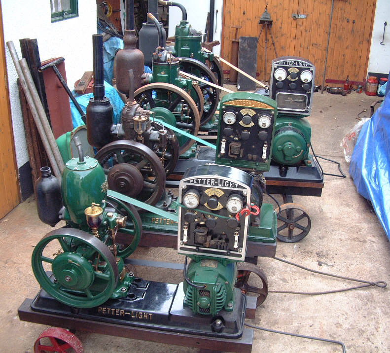
Here is a picture of four sizes of belt-driven sets
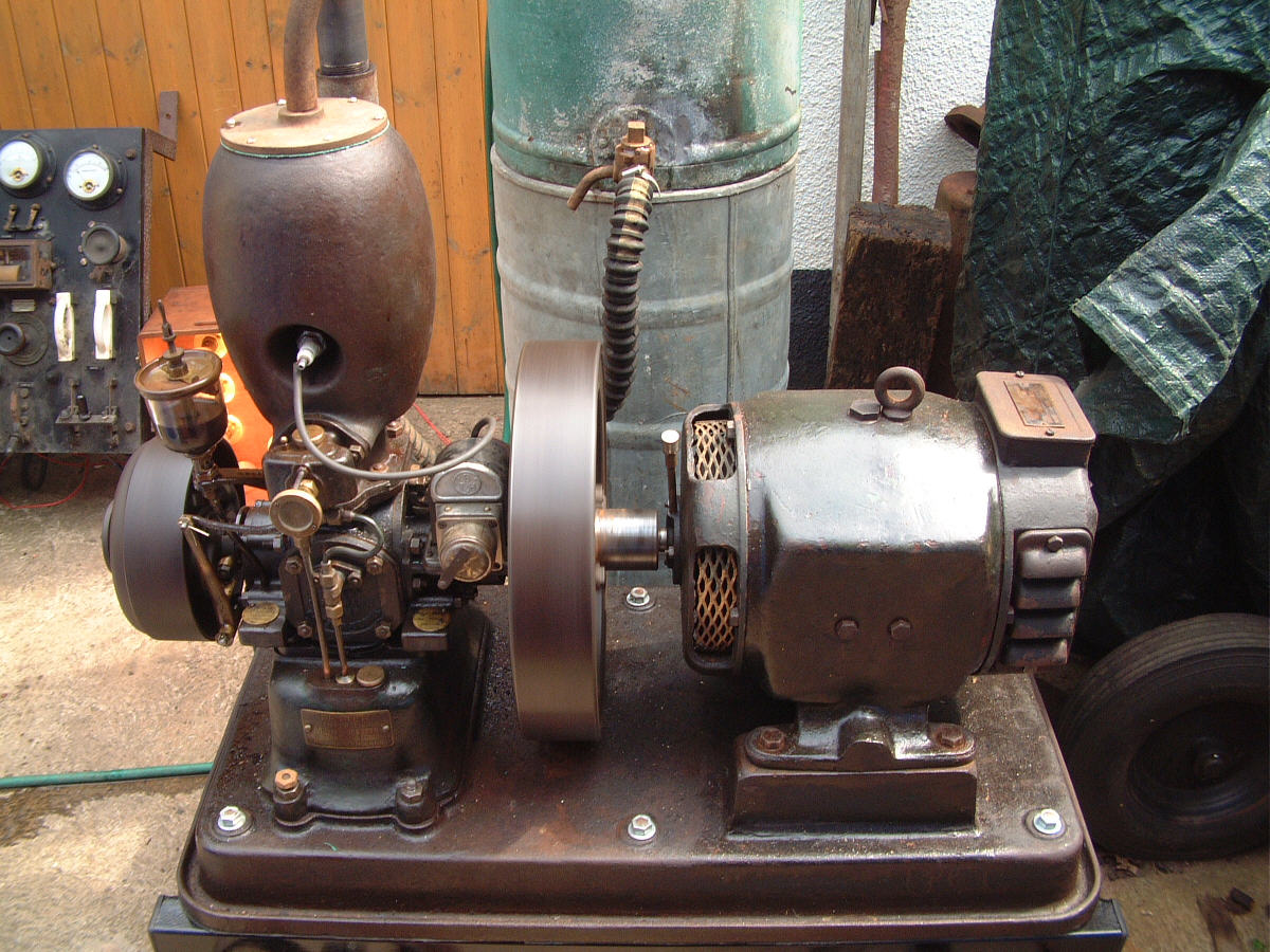
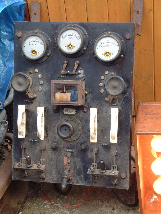
and a just-completed 1KW direct-coupled
set and its board which was supplied by
the installers. Engine number 7141 supplied to Indian & East Car Company on
12/12/29