Petter M type 5 horsepower - Bearings and Lubrication |
Initially the big end journal was 1 5/8" diameter and splash lubricated via a pick up hole in the connecting-rod cap. A brass (sometimes nickel plated) level plug was provided so that the correct oil level could be maintained in the base of the crankcase. The oil was supplied through the reed valve by a straight glass oiler possibly bought in from R*S. The plain whitemetal main bearings were lubricated by grease supplied from a reservoir attached to each main bearing housing. Initially the reservoirs appear to have been spring loaded brass (again probably off-the-shelf R*S items) and these soon gave way to Stauffer No.4 greasers in either brass or steel. Some models (especially Petter-light sets) were fitted with fluted cast spring-loaded greasers also by Stauffer and fitted with a brass ended tell-tale. Presumably engines so fitted were destined for long periods of unattended working.
After a very short time the oil supply was moved to a second chamber added to the carburettor and dripped in via a pipe into a drilling in the reed valve housing.
On the 1918 Victory model the main bearing lubrication remained unchanged. However the adoption of the patent diaphragm pump and the new carburettor necessitated a change to a separate cast oil pot bolted to the upper starting side of the crankcase. The diaphragm pump took the place of the old combined pump/reed valve housing with the new style reed valve housing replacing the blanking plate at the rear of the engine. The oil intake therefore shifted to the rear of the engine through a hole in the reed valve housing.
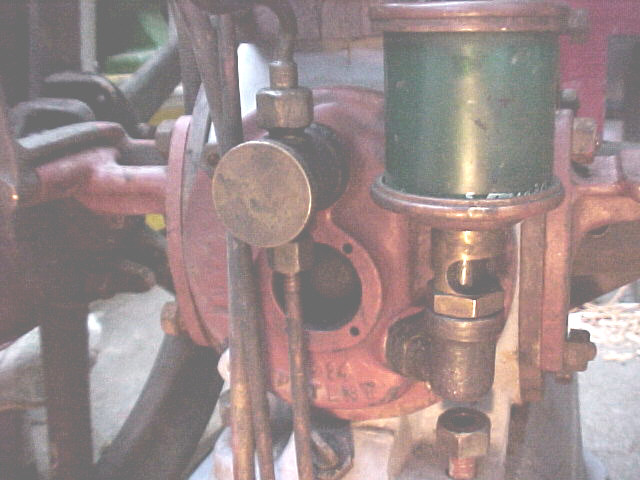
Presumably problems were being experienced with greased main bearings (today Hoyt shudder at the mere thought of it!) especially as one-off higher revving engines were probably being ordered. For the 1922 model a complete redesign was undertaken. The oil was contained in a new cast bottle fixed as before to the crankcase. There are two styles of oiler: style 1 fitted to earlier engines and style 2 fitted to later. This was pressurised by crankcase compression via a take-off in the starting side main bearing housing. The latter were slightly modified to delete the grease feed drilling , add the pressure take off boss, and create two new drillings for the new oil feed pipes. The oil was fed through a pair of drippers on the new bottle with a pipe connecting each dripper to each main housing. Each main bearing journal was scrolled and drilled through the crank web to a common output hole in the big end journal (now increased to 1 3/4" diameter). At the same time the pick up hole and annular groove in the big end shell were deleted. The reed valve housing remained drilled but was fitted upside down and the oil level plug tightened hard and filed off flush. In practice this system must have proved far too error prone and virtually impossible to correctly adjust.
It is also essential to remember to release the oiler pressure on stopping and retighten the oil pot lid before restarting. Failing to release gives a crankcase full of oil and no ready means of draining it. Failure to retighten gives zero pressure and no oil supply. I can only imagine many failures and much cursing and this system (also fitted to 1 1/2hp and 2 1/2hp engines) was abandoned after less than one year.
Capitalising on the good points of the previous system Petters introduced the 1923 model in late 1923. This has ring oiled mains and a scroll fed big end from the starting side main only. The main bearings retain the same basic dimensions but are now partially scrolled to facilitate oil movement and the ends are cut away to accommodate the oiling rings. The rings rest on the crankshaft and in rotating transfer oil from the well below to the scroll in the main bearing. **Caution: this means the bearings are handed and cannot be randomly swapped about** . New main bearing housings were designed to incorporate the oil wells and a brass inspection plug to allow a check of oil ring rotation to be made. The oil wells were closed by brass sliding lids. The starting side housing has a drilling to allow its oil level to be maintained from a cast oil pot as used on the Victory model.
Sometime in 1924 the cast oil pot was replaced by a wineglass oiler on a new cast bracket. In early examples the recommended "drops per minute" rate (20) was shown on a small brass plate screwed to the oiler bracket. Later this was replaced by directly stamping the legend into the brass top of the oiler.
In late 1931 (ish) it appears that the oil well lids were replaced by screw in aluminium caps. Although soon rendered uneceesary by the 1932 model this feature was often retrofitted to earlier models during factory rebuilds and it in this role that it is now most often seen. Incidentally the old sliding covers let the water in and the oil out as any owner will readily conform!
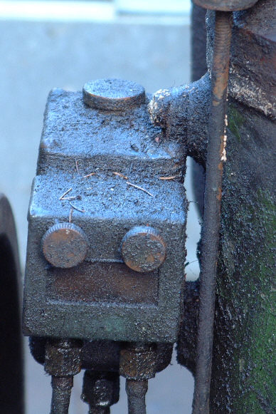
For the 1932 another total redesign was undertaken presumably with the aim of reducing the need for operator time. The main bearings were replaced by ball and roller bearings of "AMPLE!" dimensions and new main bearing housings designed to accomodate these and a felt sealing ring each side. The starting side housing contains an oilway which is fed by Petters patent Calibrater and feeds an oil gallery in the crankshaft. The latter feeds the big end journal through a web drilling. The drive side housing incorporates brackets to support the Calibrater and the magneto which are both driven by the crankshaft skew gear through a common shaft.
With hindsight it is difficult to see the commercial logic of this change which must have increased production costs when the engine's days were already numbered. Today for example the full retail price of a pair of replacement bearings is over 200UKP.