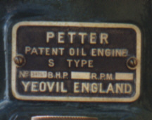
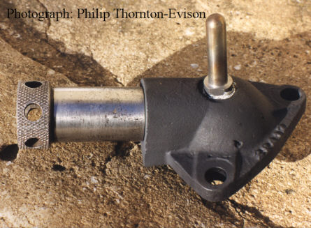
The History and development of the 5 and 8hp Petter S type Oil engines - (or musings of a Petter nut!)

The author would like to thank the following for their help:

Dave Shortland, Philip Thornton-Evison, Colin Purchase.

All content © Roland Craven unless noted otherwise.

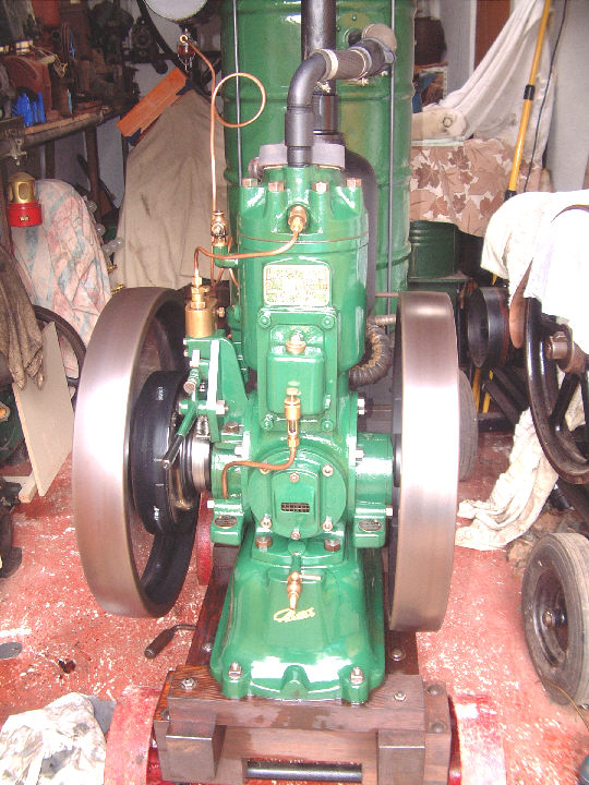
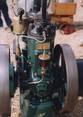
Whole engines:

#32712 The earliest 5hp so far.(Owner Richard Keyte)

vs5unknownt.jpg (10555 bytes)


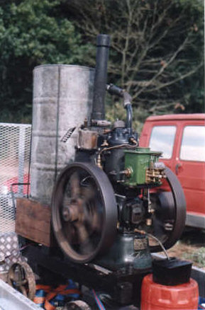
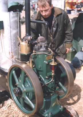
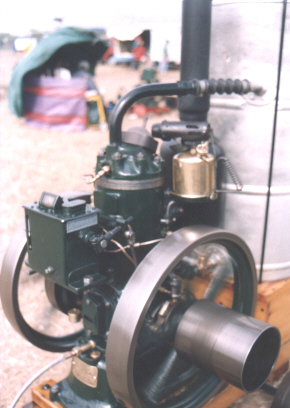
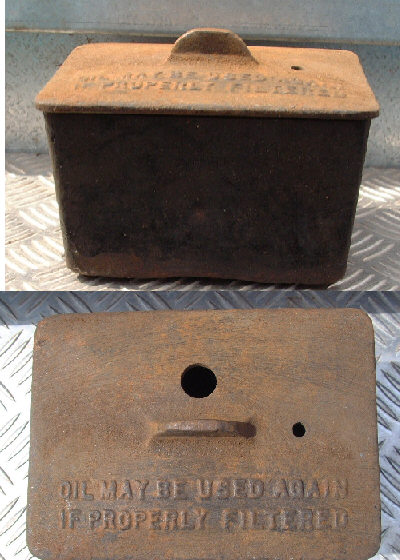
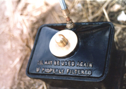
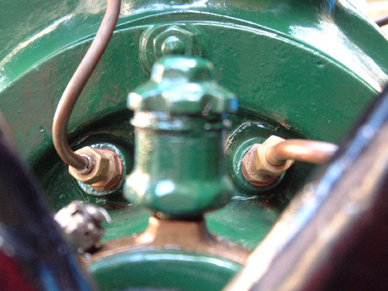
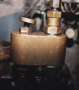
#32856 Built August 1923. Sold 18 October 1923. Rebuilt  by Petter in November 1929. Then sold to "Post als" (whatever that means?) Note the early style oil pot.

vs532856t.jpg (12954 bytes)


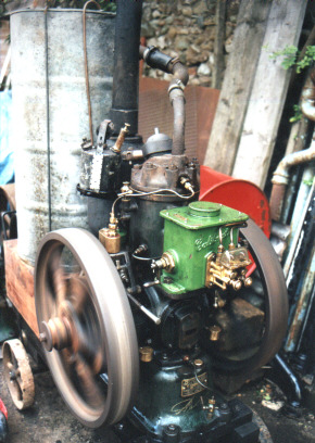
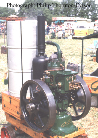
#32859 happily chuffing in the shed

vs532859t.jpg (16068 bytes)


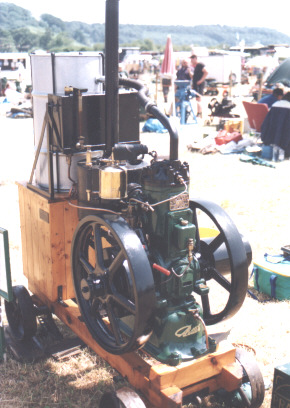
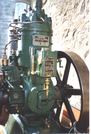
#33425 Clearly showing the wineglass oiler and undrilled base (Owner Colin Purchase )

vs533425t.jpg (12082 bytes)


#34767 8hp of 1925(All photographs of this engine courtesy of  Len Ralph). Note the shrink ring on the top of the crankcase - a standard technique then. This crankcase also has an unusual boss cast in low on the governor side.

(Owner Andy French)

vs534767t.jpg (15983 bytes)


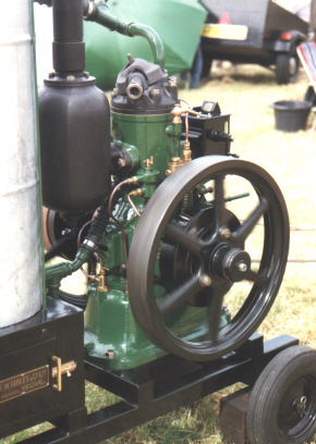
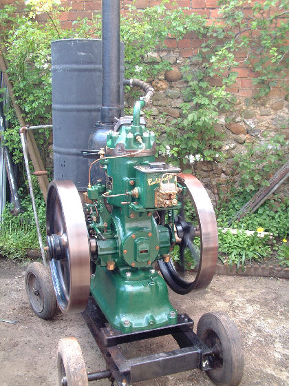
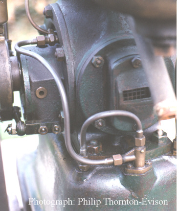
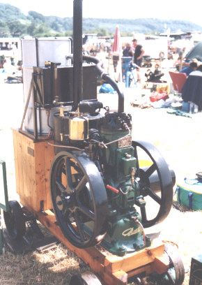
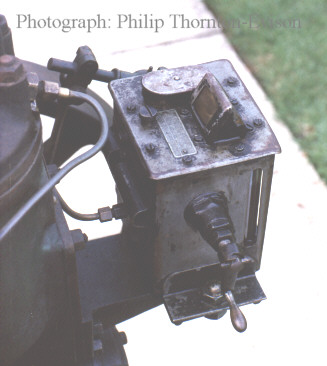
#35969 A beautiful example of a single feed Madison with the unusual lift pump.

Sold on 9 December 1925 (Owner Philip Thornton-Evison)

vs5ptet.jpg (10856 bytes)


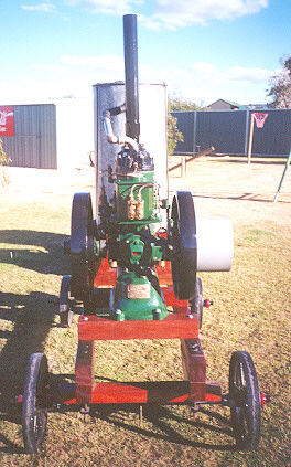
and a fine example of a generator engine (owned by Mick Christie in Australia)

PetterS Mick Christiet.jpg (9598 bytes)

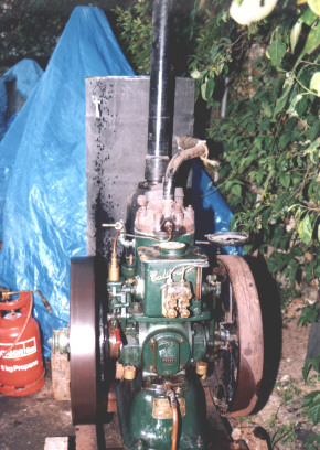
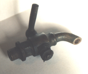
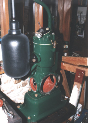
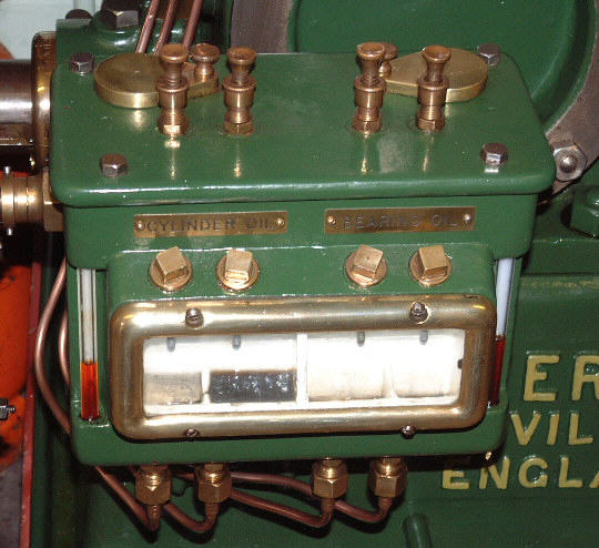
#38303 from December 1926. A fine example of a twin feed Madison engine and also showing the uncommon correct "Governer" blowlamp. (Owner Dave Shortland)

vs538303t.jpg (9943 bytes)


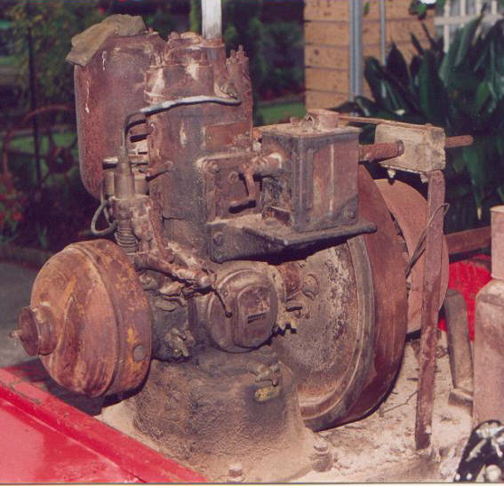
#202622 an example of a Calibrater model from 10 September 1928. Returned to the works and rebuilt in January 1931. Note the separate oil wells on the main bearings.(Owner John Ambler)

vs5202622t.jpg (11969 bytes)


and here is a nice one from Australia #205990 (Owner Russell Gilbert)

vs5205990Russellt.jpg (14567 bytes)


#211553 of 8.75hp @600rpm. Casting date 1934, Yeovil built in 1935 and sold in 1936.

vs8211553t.jpg (14320 bytes)


#213029 of 6hp. A fine example of a late, Loughborough, model from 1937. (Once owned by Dave Shortland)

vs5213029t.jpg (19679 bytes)


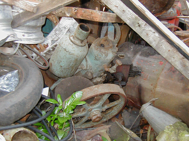
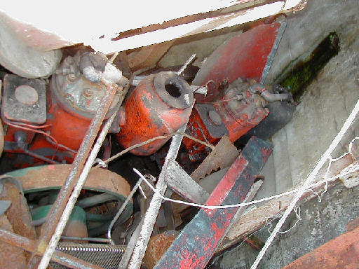
and for a bit of fun. How many S type engines and components can you find in these pictures?
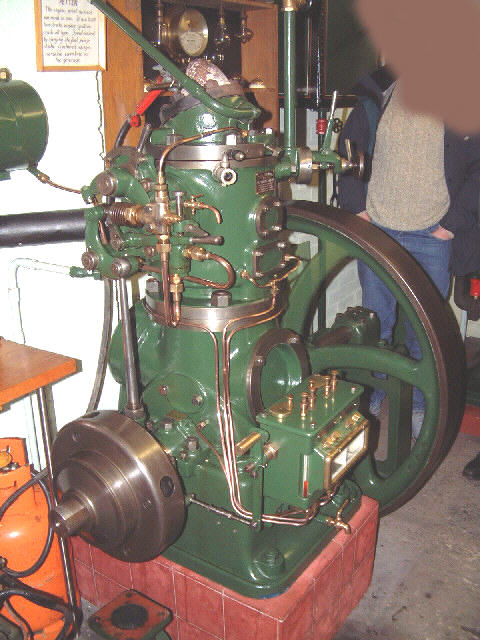
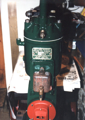
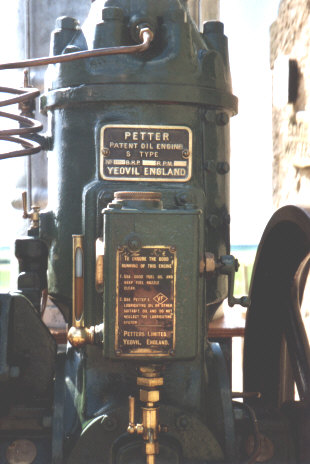
vsscrapheap1t.jpg (13867 bytes)

vsscrapheap2t.jpg (14417 bytes)

Manufacture of these beautiful engines began in 1923 and the design underwent several stages of evolution before its withdrawal in 1940. Less than 30,000 were made. Power output began at 
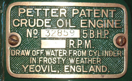
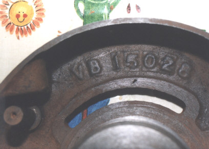
5hp (550rpm) and was later increased to 6 hp (600rpm).

The bore/stroke and many components are shared with the 5hp M type.Initial production was at Yeovil with the switch to Loughborough in about 1936 at which time the word Yeovil disappears from the nameplate. In general Loughborough engines are painted grey and have reference to Yeovil somewhat crudely ground out. As always these comments are generalisations not rules.

Most of the changes occurred in the early years with few modifications after the Calibrater version appeared in 1927. For the purposes of this paper I shall regard the, approximately 7000, pre-Calibrater engines as “early”.

Initially it was titled the "Petter Crude Oil Engine" with the first believed to be serial number 32580. It is not known exactly when this name was replaced by "S Type Oil Engine" although this did happen at or before engine #34767 (for the 8hp at least). In many ways it seems to be a scaled down type VC (#31203 - Owner Anthony Harcombe) but was actually preceded by the very rare type VB "Junior 8". (details of this may be found in SEM 246 and 252 - an instruction book is available from Patrick Knight.

These musings are based on a small sample some of which could well have been altered. Early engines are rare in original form as many were returned to the works and rebuilt to later standards. This makes tracking the development very difficult and the author welcomes contributions and especially photographs.

The many detail changes are set out below (Click the links for detail pictures then use your back button to return).

Base. The engine used much the same base as the 5hp M type throughout but appeared in four slightly different forms:

Initially a standard M base but   undrilled. A separate fuel tank was required until 1925.

Next was a version with fitments at the rear for a pump made up from parts of the M carburettor overflow fitting.

Third came the most common form with the purpose made pump but retaining the  M type small brass fuel filler cap and the front drain.

Finally the larger cast Aluminium filler cap was introduced and at the same time the crankcase drain was moved to the rear of the engine to avoid fouling the larger cap.

Crankcase. Initially any leftover crankcases appear to have been used. #32859 for example uses a Victory crankcase (and has a casting date of 11/3/1921 inside the reed valve aperture - is it original?). (Update 23/07/02 - #32712 has a crankcase dated 1920 from which the bridge has also been ground out). The cylinder oiler boss and level plug boss remain but the bridge in the transfer port is milled out.  The cooling holes in the top flange have been opened out into a figure of eight. Did they have cooling problems? Early examples have brass crankcase drain taps which are replaced in 1926 by the permanently connected waste-oil pot. There were at least two types of waste-oil pot; plain and the later type with brass fittings. The crankcase of #32859 has an extra plugged drilling in the base. Has anyone seen this before or know its purpose? (See Lubrication below for a possible explanation)

Cylinder head and Hot bulb. Few changes although early heads have rectangular section coolant ways at the flange. The early hot bulb was sealed around an inner annular ring and therefore the top face of the head was left unmachined. However later (post 1925?) bulbs have a triangular copper/asbestos gasket and the top surface of the head is machined flat. The change point is unclear and many early engines have been retrofitted with the later gasket. Presumably the early type suffered from cracked hot bulbs due to overzealous tightening.

Exhaust pot. #32712 has cast ground exhaust pot which implies that the engine was designed to be solidly mounted indoors. Later a few examples of a one piece pot are seen (on #35869 and #34767 for example). These are thinner, lighter and well demonstrate Petter’s casting skills. The top thread bears a separate part number and appears to have been pre-made and cast into the main pot. (# 32859 shows this type and also has a reducer which must surely have strangled the exhaust). By late 1924 or early 1925 the familiar three bolt pot appears as it did on the contemporary 5hp M. The screw top style of pot seems not to have been used for the S type. (possibly because they were not designed as portable engines?)

Cold start tube. Internally the same throughout but earlier examples have a thicker knurled end which seems to have disappeared in the 30’s. Presumably to save material and machining time. Again the change point is unclear, however the Petter drawing from 1936 shows the later style.

Main bearing housings. To begin with these were virtually identical to then current 5hp M with the cast-in oil reservoirs and ring oilers. The covers were initially cast iron and were later changed to Aluminium. The pulley side look to have come straight off the M production line complete with magneto bracket machining and dowel hole. The governor side casting has the addition of the spray pump stand. In these models the big end is lubricated by the governor side main journal scroll. The crankshaft bears the standard M part number and has been machined to accept balance weights.

With the first mechanical lubricator in late 1924 (?) the switch was made to the familiar plain housings with separate reservoirs screwed into the front of the housing soon added. Engine  #34767 suggest that at this time also the crankshaft oil gallery was introduced. (Note the style of main bearing housing on #34767 has only been seen on 8hp models).

Cylinder oiling. The early M-like engines have no positive cylinder oiling and relied on splash. They may have suffered high bore wear and runaways due to forgetful operators failing to drain excess crankcase oil with sufficient regularity and before starting. Such events are not unknown on the rally field today. It seems Petter were aware of this problem since #34767 has a small brass tag near the tap bearing the legend "DRAIN OFF OIL FROM CRANKCASE BEFORE STOPPING". Sound advice to which I would add - and before starting!

Lubrication. The first engines had a cast dripper, borrowed from the Victory M, bolted to a plain transfer port cover. This was soon replaced by the wine glass oiler from the contemporary M type. In #32859 and #33425 this feeds the pulley side main bearing housing and thence the big end through a crankshaft scroll. However in the case of #32712 and another of similar age the dripper is piped through the main housing to feed an oil ring bolted to the crankshaft. No provision seems to have been made for a check valve in the oil line and therefore crankcase   pressure forces the oil out and leads to oil starvation - with inevitable consequences. (Richard has circumvented the problem by dripping oil into the rear reed valve housing as on pre 1922 M types).

From 1924 until mid 1927 Petter experimented with automatic lubricators:

It is believed that for a very short time a pressure operated dripper, similar to that abortively fitted to some M types in 1922, was used.

This was followed by a pressure operated in-house design. A port was cast integral with the transfer port cover and a ratchet wheel operated by a piston driven by crankcase compression. This device was, and is, unreliable and noisy. Only about half a dozen are known to survive including #34767 (8hp dated 1925), #35050 (5hp owned by Alan Barratt) and #35553 (once owned by Dave Shortland and dated June 1925).

The experiment with these lubricators seems to have been short lived and thereafter mechanical operation was preferred.

A Manzell appeared briefly in single feed form.

A Madison-Kipp was used from late 1925. For a short period in single feed (example from #35969 opposite) and then in twin feed form to supply both the  crankshaft oil gallery and the newly added cylinder oiler . (Example is #38303 from December 1926).

From about mid 1927 the familiar Petter Calibrater became the standard and #39995 is believed to be one of the first Calibrater examples. For each different lubricator a different bracket was made to fit on the transfer port cover. The Calibrater is operated by a split bronze bush running on a flanged crankshaft eccentric. The earlier mechanical lubricators were operated by a one piece bush running on a plain eccentric and the anchor rod bracket was crudely bolted to the main bearing housing. Later the main bearing housing casting was altered to incorporate an anchor point. Various types of oilers and pressure greasers have been fitted to the bronze bush. (see A and  B)

Why did Petter go to such extraordinary lengths when they could simply have continued using the Empire lubricator that served so well on the earlier V types. The most probable answer is cost. The S was always an expensive engine  and the additional; cost would probably have rendered it unaffordable.

Bearing material. Initially solid whitemetal. Later whitemetal-lined bronze shells were used. Certainly from 1931 when the Calibrater M was introduced and possibly earlier. Stamps on some shells suggest these were bought in from Glacier.

Flywheel. Early examples have a modified version of the 5hp M flywheel which is more heavily dished and has thicker and more heavily webbed spokes at the hub to support the governor housing (note also the groove in the spoke which aligns with the TDC mark on the governer housing). The pulley side is a standard M flywheel with the balance masses machined away.

Crankshaft  The early engines appear to have used the standard 5hp M crankshaft machined for balance weights. These crankshafts are too short for the thicker, governor side flywheel hub and do not project far enough for the usual starter collar stud. The difference is made up by a 1 1/4 inch long spacer rod with a stud on each end. This had disappeared by late 1925 and possibly earlier. At this time an engine exists (#35969)with a crankshaft made by LAYSTALL. After this date Petter presumably made the new longer crankshaft in house.

Fuel lift pump. Not fitted to very early models. By #34767 at the latest a pressure operated pump appears on the base with the pressure take-off on the pulley side main bearing housing. The pump is made up from parts of the M diaphragm pump and carburettor drain flange. By 1926 the now familiar pump has appeared. (see also Base above.)

Spray pump.  Initially machined from a single block of Manganese-Bronze these were later made in two parts. The relief valve position shifted from the inside rear to the rear face (or was this repair of a manufacturing error?). Bleed cocks were small brass taps gradually replaced by knurled top ball valves. The latter began as brass and in the 1930s became steel.

Name plate. The first few hundred had a cast nameplate like the M and mounted in the same place (high on the front). With the introduction of the mechanical lubricator it was moved down to the front of the base tank and later still up to the side of the crankcase below the half compression cock. A pressed plate seems to have been introduced early on but both styles appear over a long period.

Blowlamp bracket. Starts on the governor side but switches to the pulley side in about 1925 or 1926. The same cast stand was retained throughout. Note however that #32712 has a fabricated bracket whilst that of #32859 is missing.

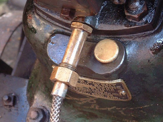
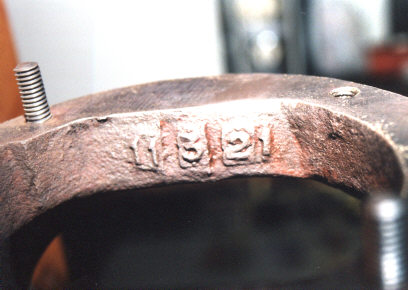
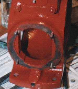
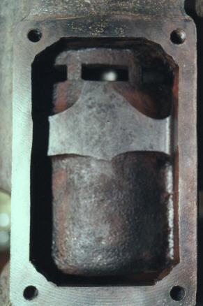
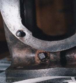
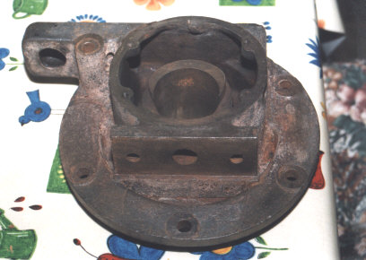
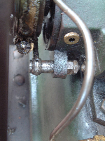
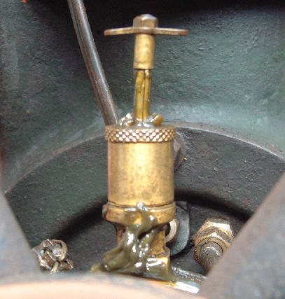
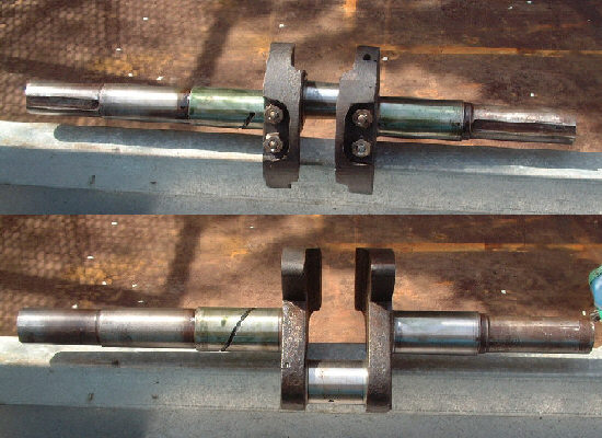
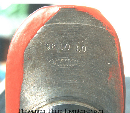
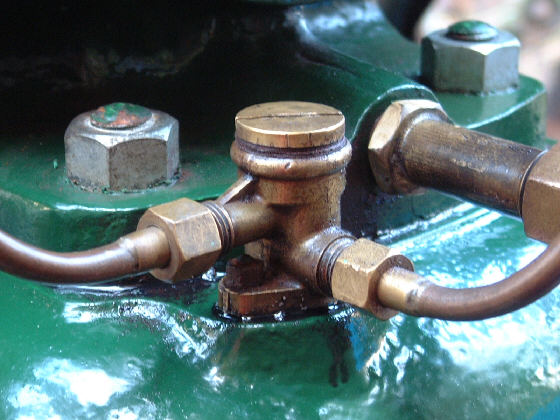
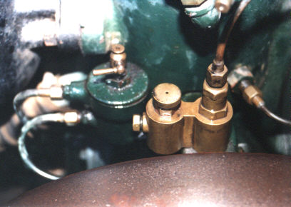
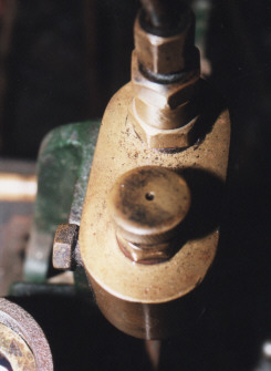
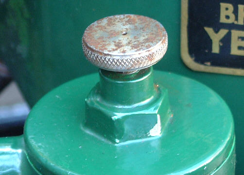
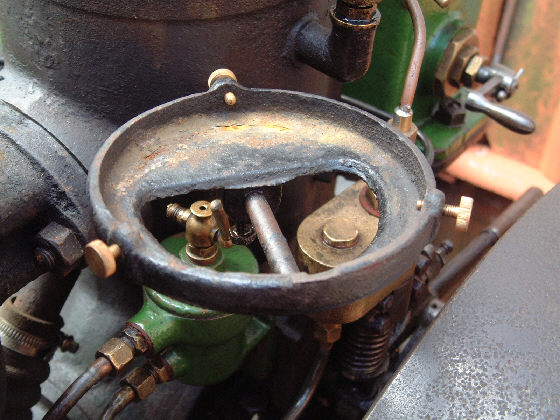
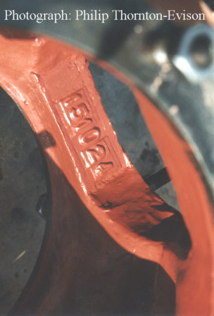
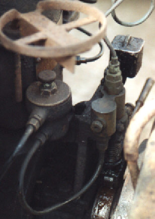
Notes on casting dates: Usually, but not always, these may be found, in DDMMYY format, cast just inside the rear reed valve housing aperture. As was normal practice then castings were typically aged for about six months before they were machined. However gaps of many years are known between casting and build dates.

The spray pump cam roller-shaft must always been prone to wear and around 1930 Petter added an additional lidded wick-oiler above the fuel priming handle. This discharges through a copper pipe onto the roller pin and the excess lubricates the roller itself. The pump bracket was modified to provide a mounting point. The earlier wick oilers were cast brass but were later changed to cast aluminium no doubt as the new skills were acquired for the A1. At about the same time the fuel filler cap and fuel filter were also changed to cast aluminium.

Finally a puzzle.

Engine 32859 (5hp) has a variety of part numbers including; five digit numbers in the 20,000 range, VF, VB and VFB.One might assume that these were shared with the 5hp M type (VF) and the 8hp M type (VB). However the governor housing of #32859 has a cast in part number beginning VB. Clearly this cannot have been shared with the big M and later housings do not carry this number.

Could it be that the big M was intended to be a compression ignition engine, or direct injection at any rate, and was released in its familiar form only as a stopgap? It was certainly dropped as soon as the 8hp S type was in production and the VS designation applied to the S type seems to appear only in later records.

Might it be relevant that the later Hamworthy engines from the same designer are direct injection and use a similar governor?